
How to Size a Differential Drive Module for a 6–8 Ton AGV
Selecting a differential drive module for a heavy-duty AGV starts with the vehicle, not with a load-capacity number in a catalog.
For a 6–8 ton platform, we normally want to understand three things first: how much force is required to move the vehicle, how much of the vehicle weight is actually carried by the driven wheels, and what happens during turning and repeated operation.
Motor power is important, but it does not answer those questions by itself.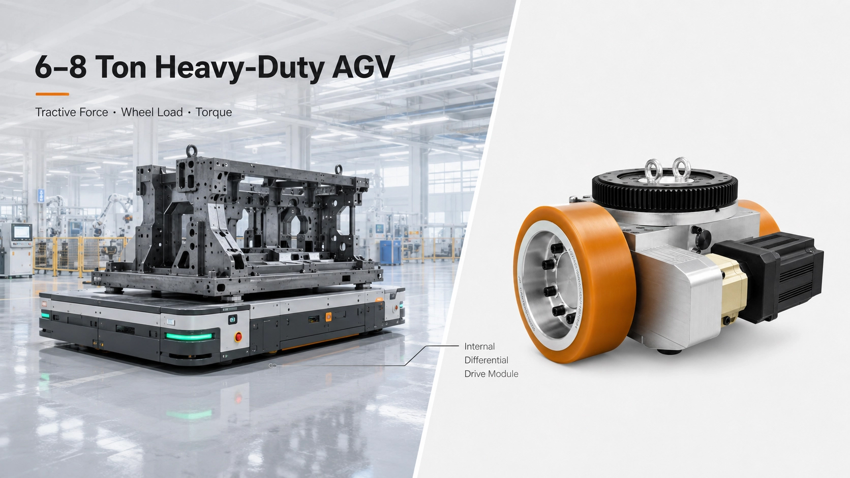
1. Start With Gross Vehicle Weight
Payload and gross vehicle weight are not the same.
For drivetrain selection, the starting point is:
GVW = vehicle self-weight + maximum payload
If a chassis weighs 1,500 kg and carries up to 6,000 kg, the gross vehicle weight is 7,500 kg.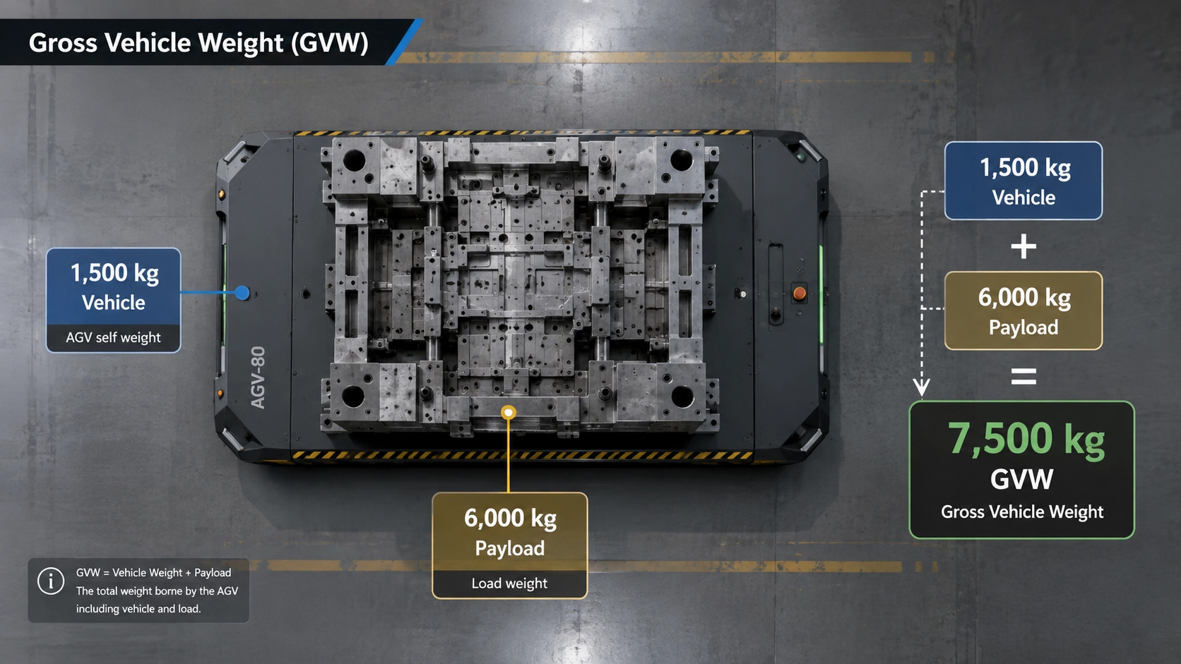
That difference matters on a heavy-duty AGV. Batteries, structural frames, lifting mechanisms, electrical cabinets and other equipment can account for a significant part of the total mass.
An “8-ton” drive module should therefore not be selected simply because the finished AGV is expected to weigh around 8 tons.
The next question is how that weight must be moved.
2. Define the Actual Operating Condition
Most heavy-duty indoor AGVs are designed around operation on relatively level industrial floors.
For that reason, we normally begin with the real straight-line operating condition rather than assuming a generic slope or other worst case.
At a basic level, the required tractive force includes the force needed to overcome rolling resistance and to accelerate the vehicle:
F ≈ Frolling + Facceleration
If the actual route includes a ramp or measurable gradient, grade resistance should be added as a separate condition.
Rolling resistance should also not be treated as a fixed universal number. It changes with wheel material, wheel diameter, floor surface, bearing condition, passive-wheel arrangement and vehicle load.
For preliminary selection, an estimate can be useful. For final validation, the values should reflect the actual vehicle and operating floor.
3. Convert Tractive Force Into Wheel-Side Torque
Once the required tractive force is known, the required torque at the drive wheel is related to wheel radius:
Twheel = Fwheel × r
This is wheel-side torque, after the gearbox.
Wheel diameter therefore affects more than vehicle height. A larger drive wheel requires more torque to produce the same tangential force at the floor, while also influencing vehicle speed and floor-transition capability.
Motor torque, gearbox ratio, drivetrain efficiency, wheel diameter and target speed should be considered together.
For a symmetric two-wheel differential drive, dividing the total tractive-force requirement between the two driven wheels can be used as a preliminary estimate. The final design should still consider the actual mechanical layout and control strategy.
4. Drive-Wheel Load Can Be More Important Than Motor Size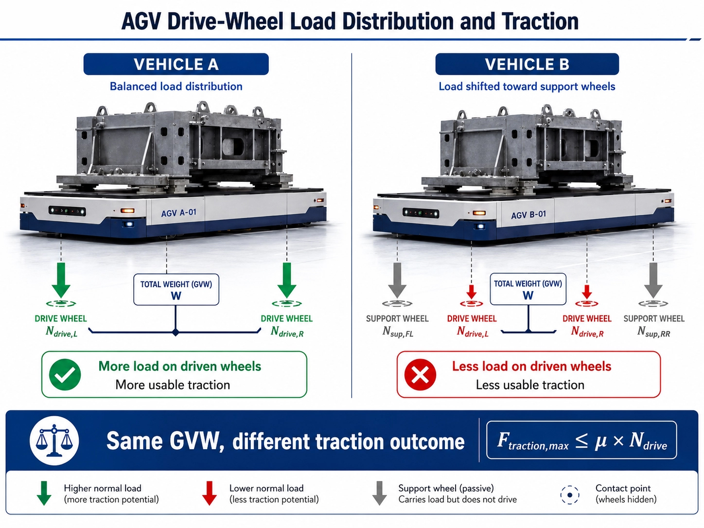
A common mistake is to respond to insufficient traction by increasing motor power.
That does not always solve the problem.
The force that a drive wheel can transmit to the floor depends on both wheel–floor friction and the vertical load carried by the driven wheels:
Ftraction,max ≤ μ × Ndrive
This is why two AGVs with the same gross vehicle weight and the same motors can behave differently.
If a large proportion of the vehicle weight is carried by passive support wheels, the driven wheels may not have enough vertical load to use the available motor torque effectively.
In that case, additional torque can lead to wheel slip rather than additional usable tractive force.
Battery location, payload position, center of gravity, support-wheel placement and drive-module position all affect this result.
For heavy-duty differential-drive platforms, drive-wheel load should therefore be checked as part of the chassis design—not after the motor has already been selected.
5. Straight-Line Travel Is Only Part of the Problem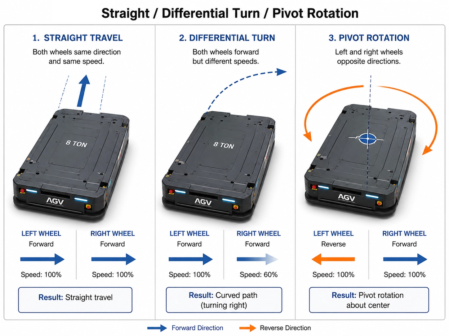
A differential-drive AGV does not operate only in a straight line.
During a normal turn, the left and right drive wheels run at different speeds. During a pivot turn, they may rotate in opposite directions.
This introduces a different mechanical condition from straight travel.
On a heavy vehicle, turning resistance can be affected by wheel material, floor condition, support-wheel position, wheelbase, track width and payload distribution. Tire scrub and deformation can also increase motor current and drivetrain load.
This is one reason we do not consider a straight-line tractive-force calculation sufficient for final module selection.
A vehicle may travel comfortably in a straight line but place noticeably higher demand on the drivetrain during repeated low-speed turns or pivot rotation.
The chassis layout needs to be evaluated together with the drive module.
6. Check the Duty Cycle
Peak torque tells only part of the story.
Two AGVs can have the same maximum weight and travel speed but very different operating duty.
One may travel long distances with few stops. Another may start, stop and turn repeatedly in a short production cycle.
For drivetrain review, we normally look at four groups of information:
Load
typical and maximum gross vehicle weight
Motion
travel speed
acceleration and braking
start/stop frequency
turning and pivot-turn requirements
Environment
floor material and condition
floor joints or transitions
ramps or gradients, if present
ambient temperature
Duty
continuous or intermittent operation
expected operating hours
frequency of high-load manoeuvres
These conditions help determine whether the motor and gearbox are being selected for an occasional peak or for a load they must handle repeatedly.
7. Do Not Use a Universal “Safety Margin”
A preliminary calculation normally includes some allowance for uncertainty.
However, we do not recommend treating one fixed percentage as a universal rule for every AGV.
The appropriate margin depends on how accurately the vehicle mass, wheel load, floor condition, motion profile and duty cycle are known.
Oversizing also has consequences: larger motors and gearboxes increase current demand, package size, battery requirement, weight and cost.
The objective is not to select the largest available module.
It is to select a drive system that can handle the real operating condition with reasonable engineering margin and then verify it on the vehicle.
8. Application Example: A 7.5-Ton Heavy-Duty AGV
Suppose we receive an application with the following initial information:
| Parameter | Application Data |
|---|---|
| Vehicle self-weight | 1,500 kg |
| Maximum payload | 6,000 kg |
| Gross vehicle weight | 7,500 kg |
| Drive concept | Two-wheel differential drive |
| Target drive-wheel diameter | 300 mm |
| Operating environment | Indoor industrial floor |
This is enough to define the vehicle weight class.
It is not enough to make a final drivetrain selection.
Before confirming the drive module, we would still want to know:
How much vertical load is carried by the two driven wheels?
Where are the passive support wheels located?
What are the target and maximum travel speeds?
What acceleration is required?
Does the AGV need frequent pivot rotation?
What wheel material and floor surface will be used?
Are there floor joints, thresholds or ramps on the route?
What is the expected operating cycle?
What installation space is available?
What power supply and control interface are required?
This information usually tells us more about the suitability of the drive system than the statement “the AGV weighs 7.5 tons.”
9. How to Interpret an 8-Ton-Class Differential Drive Module
JY Robot offers a heavy-duty dual-wheel differential drive module in the 8-ton load-capacity class, with a rated total tractive force of 3,795 N.
Those two specifications describe different aspects of the module.
Load capacity relates to the mechanical load the module is designed to carry.
Rated tractive force describes its continuous drive-force capability under the specified product conditions.
Neither value should be used alone to conclude that the module is suitable for every 8-ton AGV.
For a particular vehicle, we still need to compare the module with the required tractive force, driven-wheel load, wheel diameter, turning behaviour and duty cycle.
This is why we treat the 8-ton rating as a starting point for application review—not as a complete vehicle-selection rule.
10. Information to Prepare Before Selecting the Module
For a 6–8 ton AGV, the following information is normally useful for an application review:
Vehicle self-weight and maximum payload
Expected gross vehicle weight
Drive-wheel vertical load or chassis load distribution
Target and maximum travel speed
Acceleration requirement
Drive-wheel diameter and material
Floor material and condition
Support-wheel arrangement
Turning and pivot-rotation requirement
Route gradient or ramps, if any
Installation envelope
Battery voltage
Motor-control or communication requirement
Typical operating cycle
A chassis drawing is particularly useful because drive-wheel load and support-wheel placement can often be reviewed more effectively from the vehicle layout than from a weight number alone.
11. Final Selection Should Be Made at Vehicle Level
A differential drive module is part of a complete vehicle system.
On the drive side:
Motor → Gearbox → Wheel torque → Wheel diameter → Tractive force
On the chassis side:
Vehicle layout → Drive-wheel load → Wheel/floor contact → Usable traction
And in operation:
Acceleration + Turning + Duty cycle + Route condition → Actual drivetrain demand
These relationships are why we prefer to review the application before recommending a final configuration.
For a heavy-duty AGV, the useful question is not simply:
“Which module is rated for 8 tons?”
It is:
“Does this drive module match the way this vehicle carries its load, moves, turns and operates?”
Frequently Asked Questions
Is an 8-ton-rated differential drive module suitable for every 8-ton AGV?
No. Gross vehicle weight is only one input. Driven-wheel load, required tractive force, turning behaviour, floor condition and duty cycle also affect the result.
Should an AGV drive module be selected by motor power?
Motor power alone is not enough. Wheel torque, gearbox ratio, wheel diameter, available traction, vehicle speed and thermal duty all need to be considered.
Why is drive-wheel load important?
The driven wheels need sufficient vertical load to transmit torque to the floor. If too much vehicle weight is transferred to passive support wheels, usable traction can become limited even when sufficient motor torque is available.
What if the AGV route includes a slope?
Use the actual route gradient as an additional application condition. For heavy-duty indoor vehicles, it is better to evaluate a real ramp or gradient than to assume a generic slope during preliminary sizing.
Need Help Reviewing a Heavy-Duty AGV Application?
For an initial application review, send us:
vehicle self-weight
maximum payload
target speed
drive-wheel load, if available
support-wheel layout
floor condition
turning requirements
installation drawing
We can then review the differential drive module against the actual chassis and operating conditions.
View the JY Robot 8-Ton-Class Heavy-Duty Differential Drive Module